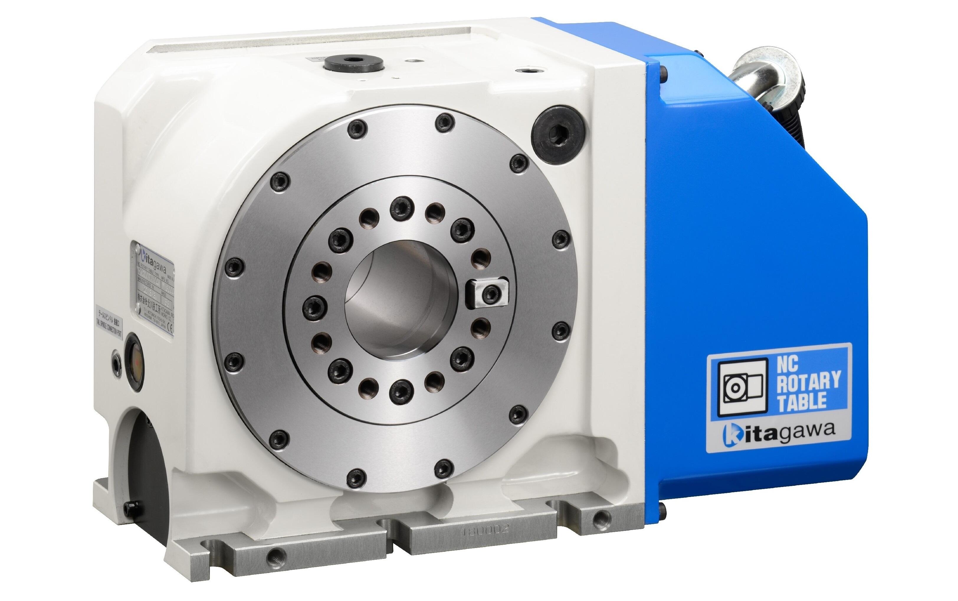
Machine Tool
*CE correspondence
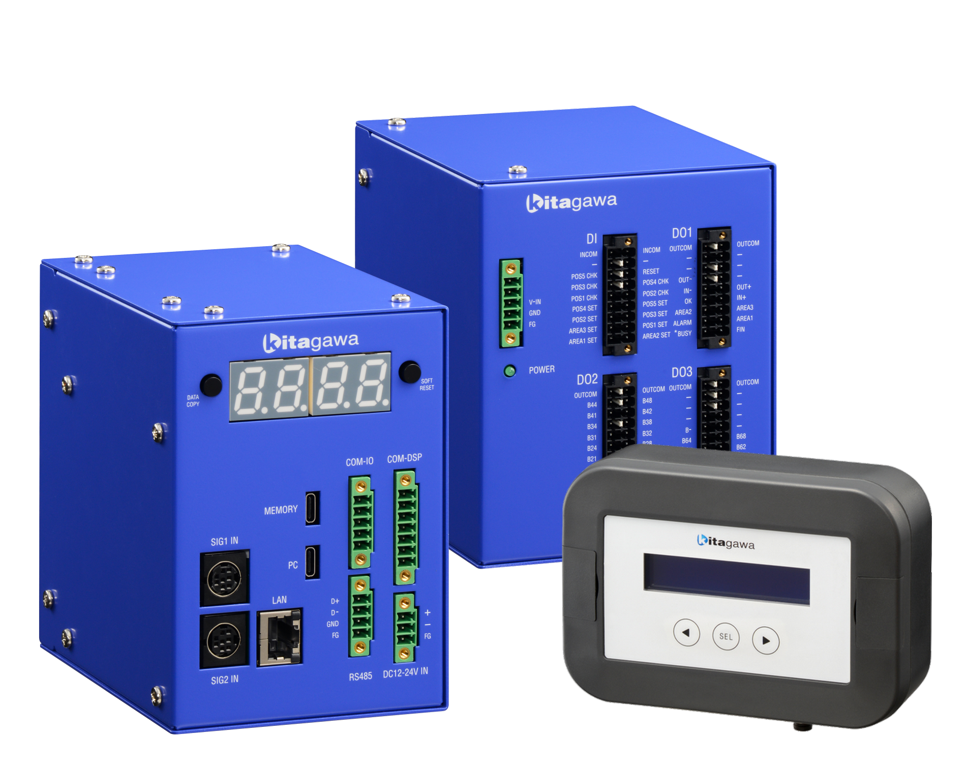
Control Unit MET-CT
| Item | Specification | ||
|---|---|---|---|
| Applicable Standard | CE | ||
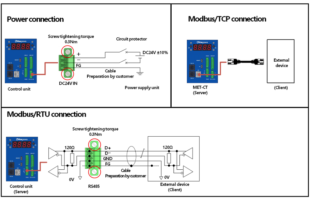
| Power Supply Voltage | DC24V | ||
| Functions |
・Numerical conversion of scale signal (Pulse → mm) ・Workpiece dimension conversion calculation considering the jaw shape (V-shape 2-jaw outer diameter measuring, 3-jaw inner diameter measuring) ・5 measuring positions (POS1 ~ 5) ・5-level judgement (OK / IN+ / IN- / OUT+ / OUT-) ・Measuring data (Measuring history) storage |
||
|
External I/O
|
Modbus/TCP Modbus/RTU |
【Input】 ・Reference position set (POS1 ~ 5 SET) ・Output zone setting (AREA1 ~ 3 SET) ・Measuring judgement command (POS1 ~ 5 CHK) ・Alarm reset (RESET) |
【Output】 ・Measuried value ・Judgement result (OK / IN+ / IN- / OUT+ / OUT-) ・In-range signal output (AREA1 ~ 3) ・Alarm (*ALARM) ・BUSY status (*BUSY) |
| USB (MEMORY) |
【Input】 ・Firmware update |
【Output】 ・Measuring history (CSV) ・Alarm history (CSV) ・Parameter list (CSV) |
|
| Display content |
・Judgement result (POS1 ~ 5) ・Alarm status, Alarm number ・Internal status |
||
I/O Signal Unit MET-SG
| Item | Specification | ||
|---|---|---|---|
| Applicable Standard | CE | ||
| Power Supply Voltage | DC24V | ||
|
External I/O
|
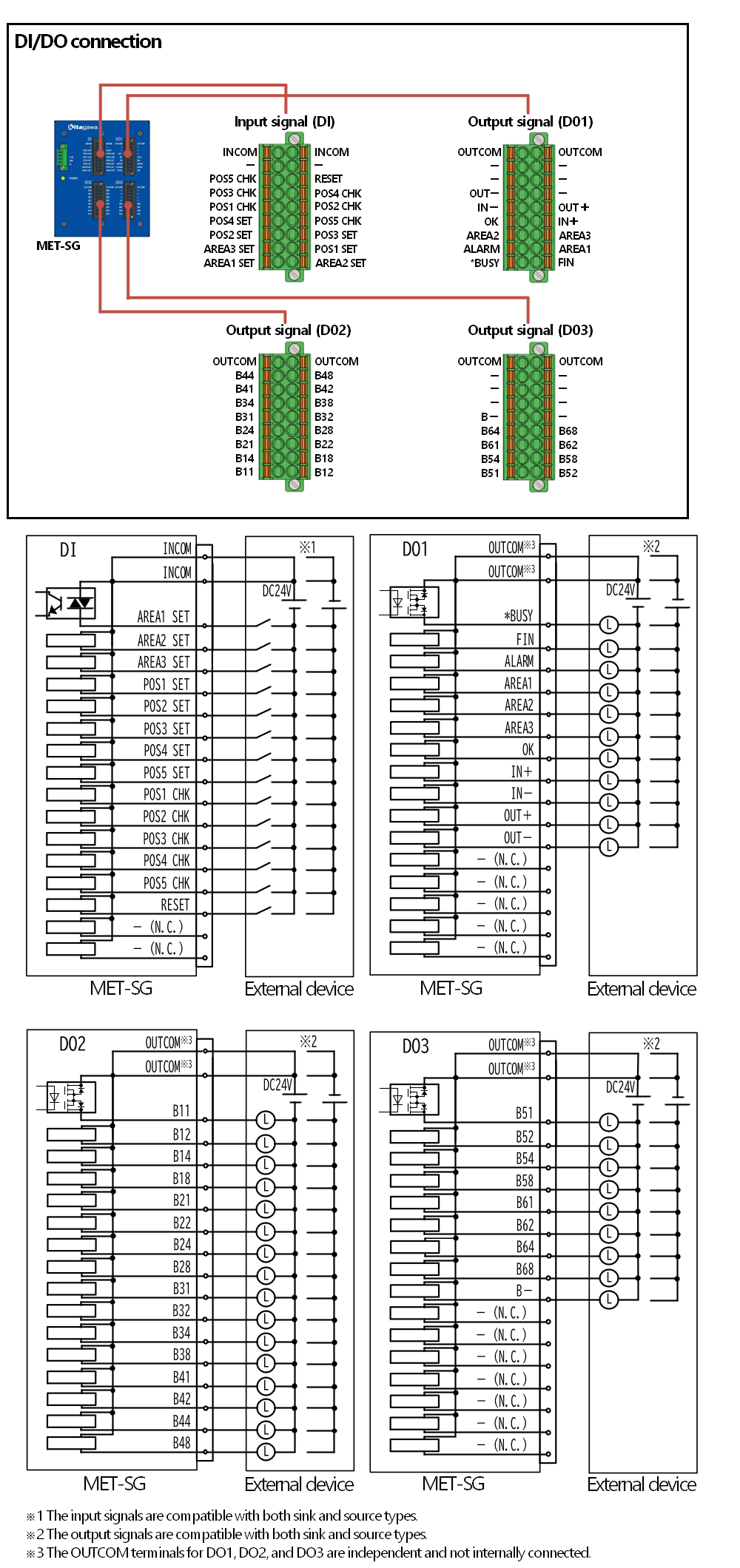
DI/DO |
【Input】 ・Reference position set (POS1 ~ 5 SET) ・Output zone setting (AREA1 ~ 3 SET) ・Measuring judgement command (POS1 ~ 5 CHK) ・Alarm reset (RESET) |
【Output】 ・Measured value ・Judgement result (OK / IN+ / IN- / OUT+ / OUT-) ・In-range signal output (AREA1 ~ 3) ・Alarm (*ALARM) ・BUSY status (*BUSY) |
Display Unit MET-DP
| Item | Specification |
|---|---|
| Applicable Standard | CE |
| Power Supply Voltage | Power supplied from the Control Unit |
| Display Content |
・Measured value (POS1 ~ 5) ・Judgement result (POS1 ~ 5) ・Alarm status, Alarm number ・Internal status ・DI/DO diagnosis |
Dedicated Software Configuration & Monitor Tool MET-MT
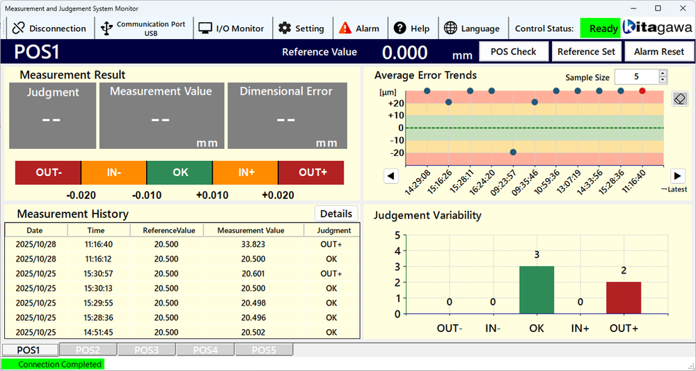
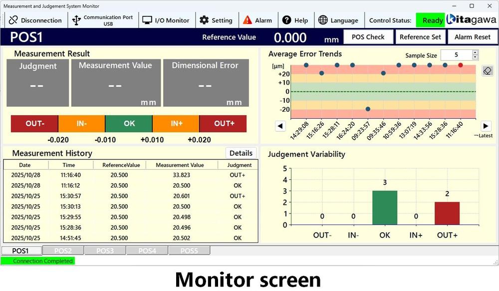
The Configuration & Monitor Tool MET-MT allows for the necessary configuration of the Measuring Judgement System , as well as the monitoring of judgement results and other information.
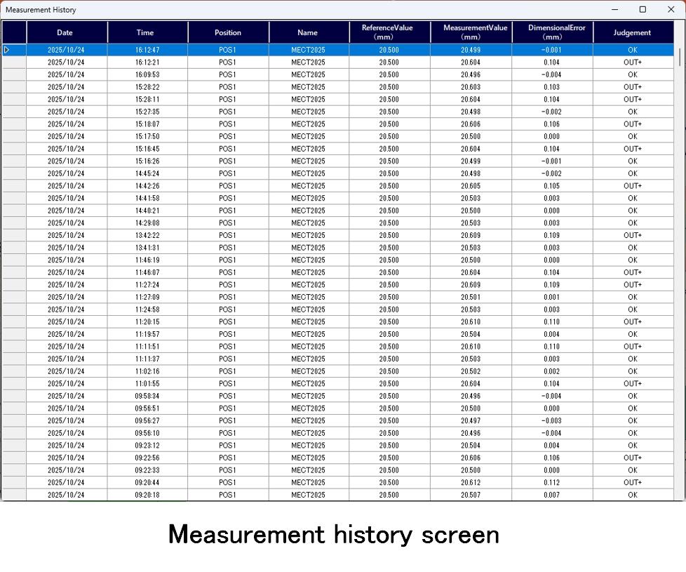
・Display of parameter settings, judgement results, and measuring history.
・Display of alarm history.
・Measuring error trend.
・Display of measuring variation trend graphs.
|
Model |
MET-CT |
MET-SG |
MET-DP |
|
|---|---|---|---|---|
| 2D |  |
|
|
|
| TIF |  |
|
|
|
| DXF |  |
|
|
|
| DWG |  |
|
|
|
| 3D | STEP |  |
|
|
Click on the image to enlarge it.
The entire table is not displayed on the screen, so please scroll to the right using the scroll button.
| No. | Name | Model | Scope of supply | Remarks | Opt.: 〇 |
|
|---|---|---|---|---|---|---|
| NPGT_S NPL_S NTS3_S |
Kitagawa | For details, please refer to the gripper catalogue and the instruction manual. Note) Either device A or B is to be selected. |
◎ | |||
| Cable with interpolator | LD***DT01DT01 | |||||
| - | - | A/B phase output compatible sensor. Note) Either device A or B is to be selected. |
◎ | |||
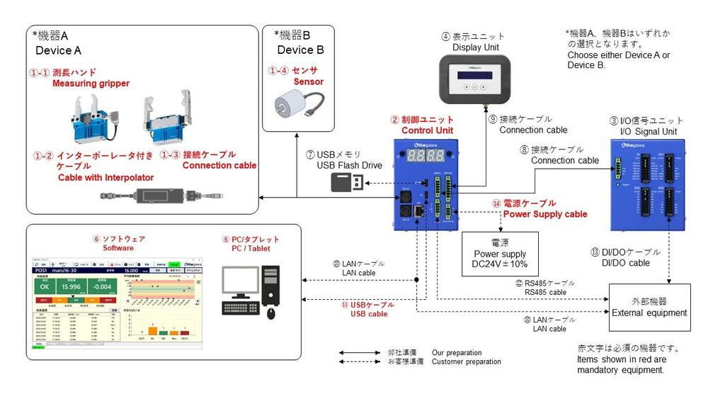
| ② | Control unit | MET-CT | Kitagawa | MET series components Modbus/RTU/TCP communication with external devices is possible. |
◎ | |
| ③ | I/O signal unit | MET-SG | Kitagawa | MET series components It is necessary when external devices and DI/DO communication. |
〇 | |
| ④ | Display unit | MET-DP | Kitagawa | MET series components It is necessary when judgement results are checked at any time. |
〇 | |
| ⑤ | PC/Tablet | - | Customer | For Windows10/11, 64-bit It is required during setup. |
◎ | |
| ⑥ | Setting & monitor tool (Software) | MET-MT | Kitagawa | MET series components Obtain from Kitagawa HP. |
◎ | |
| ⑦ | USB flash drive | - | Customer | For data output (Type-C) | 〇 | |
| ⑧ | I/O signal unit connection cable | MET-SGC-02 | Kitagawa | I/O signal unit accessories (2m) | - | |
| ⑨ | Display unit connection cable | MET-DPC-03 | Kitagawa | Display unit accessories (3m) | - | |
| ⑩ | LAN cable | - | Customer | For PC connection or Modbus/TCP communication Above Cat5e, Cross/straight |
〇 | |
| ⑪ | USB communication cable | - | Customer | For PC connection, Control unit side: Type-C | ◎ | |
| ⑫ | RS485 cable | - | Customer | For Modbus/RTU connection | 〇 | |
| ⑬ | DI/DO cable | - | Customer | For DI/DO communication | 〇 | |
| ⑭ | Power supply cable | - | Customer | DC24V | ◎ | |
Click on the image to enlarge it.
| DI | Setting | ||
|---|---|---|---|
| pos3_set | Port number | ||
| pos4_set | CM_SR | Scale resolution | |
| pos5_set | CM_SD | Scale moving direction | |
| pos1_chk | CM_SJT | Stop judgment timer | |
| pos2_chk | POS2 |
CM_SJR | Stop judgment range |
| pos3_chk | POS3 |
CM_PTO | Process time out |
| pos4_chk | POS4 |
CM_NO | Judge except consecutive OK |
| pos5_chk | POS5 |
IO_CT | Chattering protect timer |
| reset | Alarm reset | IO_FT | FIN signal timer |
| DO | IO_JT | Judgment output timer | |
| busy | Busy (Signal input unavailable) | IO_BO | BCD output specification |
| fin | Operation complete | IO_AS | Alarm signal output specification |
| alarm | Alarm | POS*_NM[CH01]-[CH20] | Name: [CH01][CH02]・・・[CH20] |
| area1 | Range ouotput 1 | POS*_MT | Measurement type |
| area2 | Range ouotput 2 | POS*_H | Hand specificparameter |
| area3 | Range ouotput 3 | POS*_RP | Standard placement pulse |
| ok | Judgement signal: OK | POS*_PV | POS* reference set |
| in_pls | Judgement signal: IN+ | POS*_PLS | POS* +threshold |
| in_mns | Judgement signal: IN- | POS*_MNS | POS* -threshold |
| out_pls | Judgement signal: OUT+ | POS*_DPLS | POS* + +threshold |
| out_mns | Judgement signal: OUT- | POS*_DMNS | POS* - -threshold |
| b11 - b68 | BCD output 1 digit 0 bit ー 6 digit 3 bit | AR_*P | AREA* standard pulse |
| ALARM | AR_*PLS | AREA1* threshold | |
| ER1_CPU | CPU error | AR_OS | Range Output Specification |
| ER1_AB_PHASE_AB | Scale A/B phase signal fault | AR_RT | Range Output timer |
| ER1_OVERFLOW | Pulse count overflow | AR_RDT | Range Output delay timer |
| ER2_SET_POS* | POS* reference set failure | SM_SN [CH01]-[CH20] | Serial Number: [CH01][CH02]・・・[CH20] |
| ER2_MEAS_POS* | POS* measurement failure | SM_VR [CH01]-[CH20] | F/W Version: [CH01][CH02]・・・[CH20] |
| ER2_SET_AREA* | AREA* set failure | Measurement value (pulse) | |
| ER2_JUDGE_POS* | Judge except consecutive OK (POS*) | Pulse1 | Pulse |
| ER2_USB_CXN | USB data output failure (not connecting USB memory) | Measurement value (mm) | |
| ER2_USB_EXIST | USB data output failure (exist same file name) | POS1 Value | POS1 Value |
| ER2_USB_SPACE | USB data output failure (Not sufficient storage) | POS2 Value | POS2 Value |
| ER2_COMM_IO | Communication error (I/O unit) | POS3 Value | POS3 Value |
| ER2_COMM_DISP | Communication unit (Display Unit) | POS4 Value | POS4 Value |
| ERS_COMM_RS485 | Communication error (external device RS485) | POS5 Value | POS5 Value |
| ER2_COMM_ETH | Communication error (external device ether communication) | POS1 Judgement | POS1 Judgement |
| ER3_POS_NOT_SET | POS not set | POS2 Judgement | POS2 Judgement |
| ER3_LOW_BATT | Battery zero | POS3 Judgement | POS3 Judgement |
| STATUS | POS4 Judgement | POS4 Judgement | |
| Status | Status | POS5 Judgement | POS5 Judgement |
User registration enables access to the latest software downloads. Notifications regarding software updates and other important information will be sent to the registered email address.
To begin the registration process, please click the link below. Upon completion of user registration, our security export control procedures will be undertaken. Once this process is complete, an email containing the link to the software download page will be sent to the registered address.

Feature 1: Workpiece dimension conversion calculation that takes the shape of the gripper jaws into account
●No dimension conversion required on the PLC
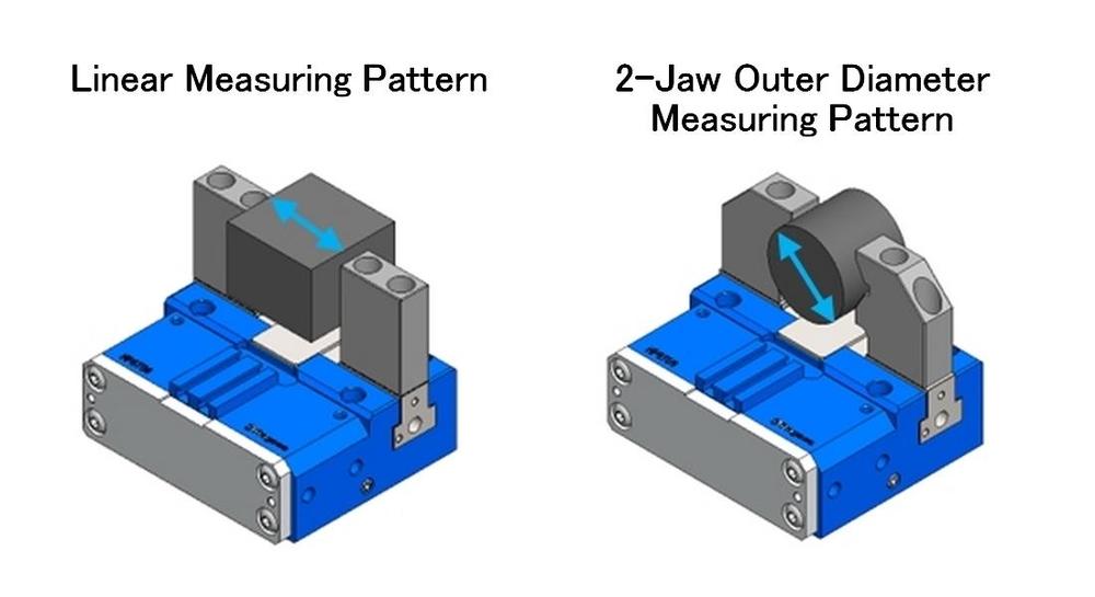
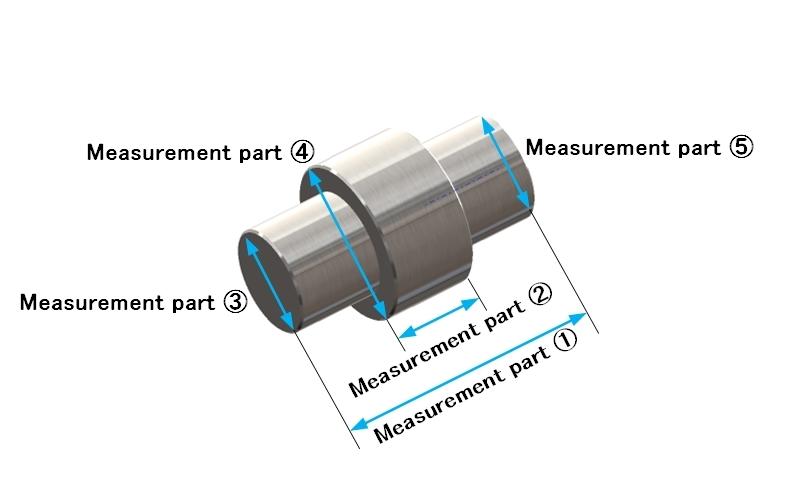
Feature 2: 5 measurement points
●Judgement thresholds can be set for each of the 5 points.
●Measuring patterns (linear or diameter) can be set for each of the 5 points.
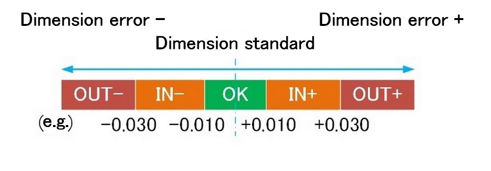
Feature 3: Measuring results output with 5-level judgement
●The measured value is judged for conformity in 5 levels according to the thresholds.
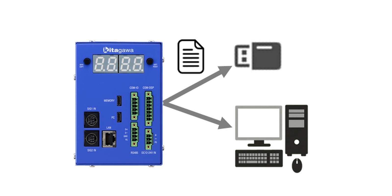
Feature 4: Measured Data Saving and Output
●Measured data is output to a USB memory stick or PC.
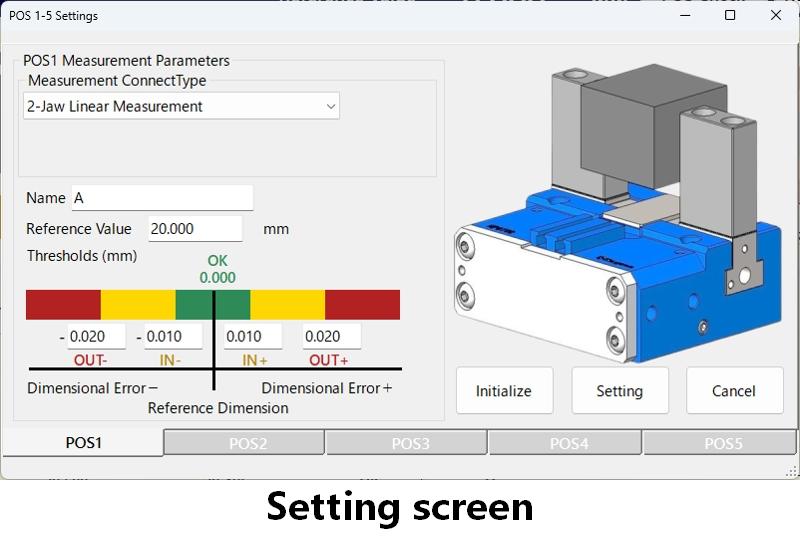
Feature 5: Easy configuration with dedicated software
●Operation is possible on a Windows OS PC or tablet.
●Configuration items are explained with graphics.
●Measured values and judgement results are displayed in real-time.
●Connection is established via either Ethernet or USB.
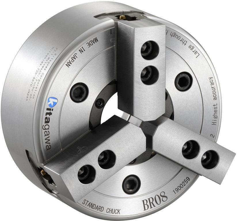
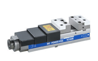
Wide variety of world’s standard power chuck
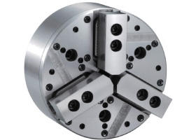
High gripping force & stability to suit various requirements
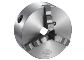
Standard Manual Chucks suit to a high-mixture of work pieces and low-volume production.
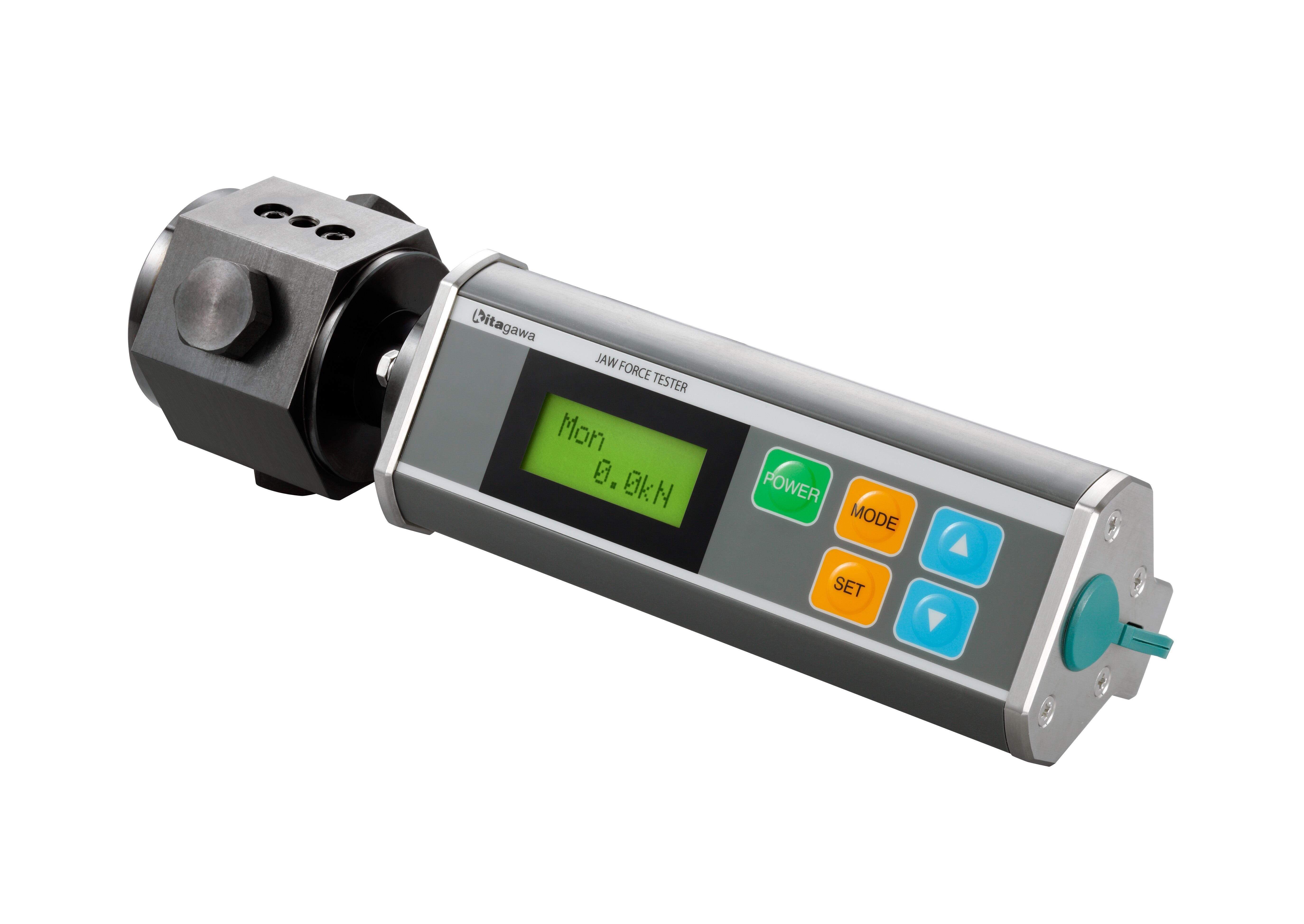
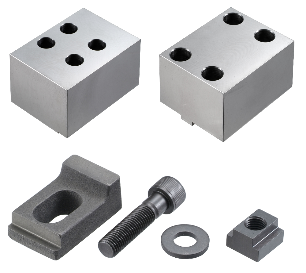
Necessary item for Quality control and Safety
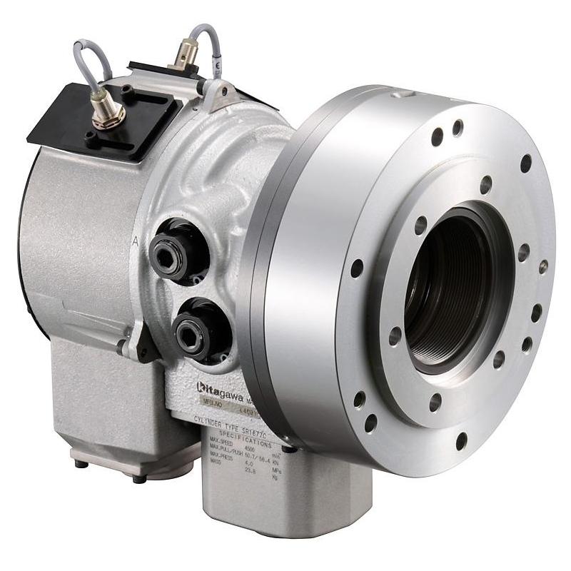
High performance Rotary Cylinder is integral to for the operation of a power chuck and extracts the maximum capability of the chuck.
Compact & high accuracy Combination with chuck is available.
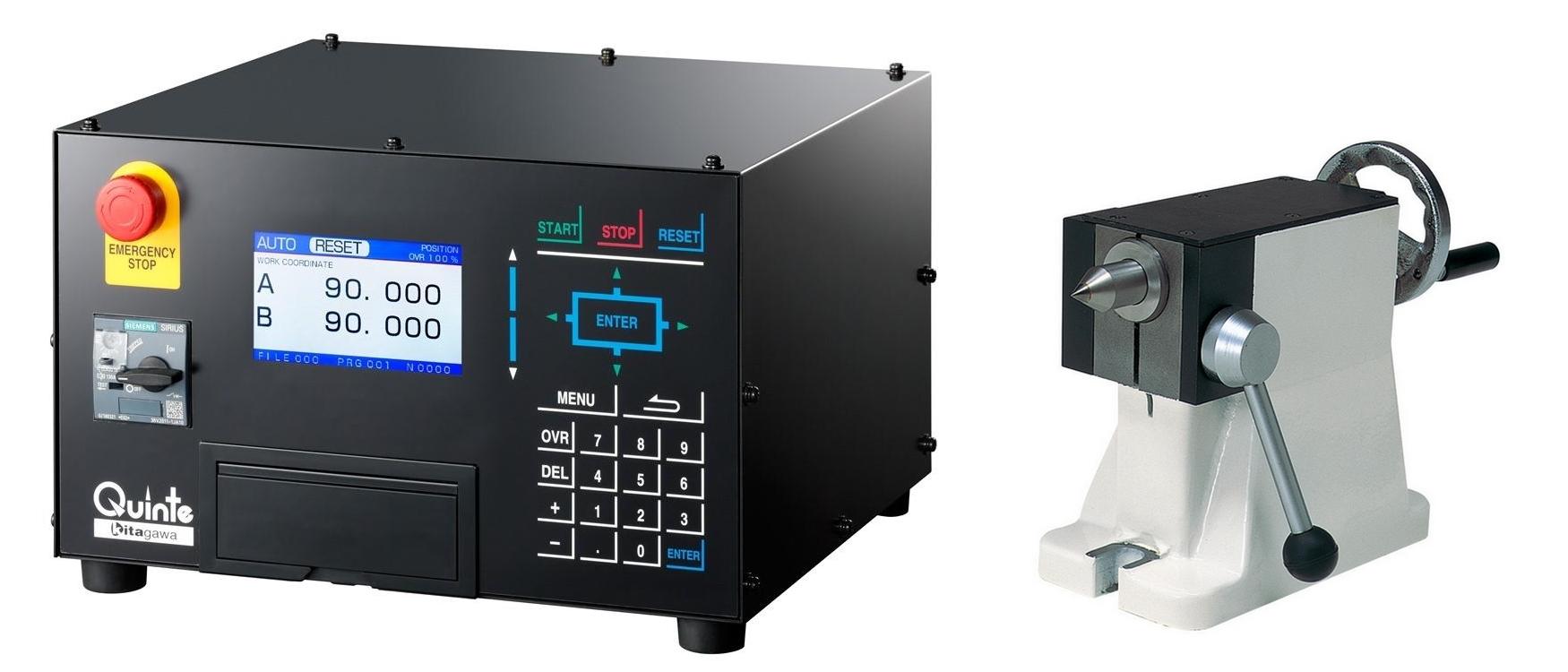
Tail stocks, tail spindles, rotary joints, rotary chucks, Dedicated controller and others
Toggle joint mechanism Long jaw stroke
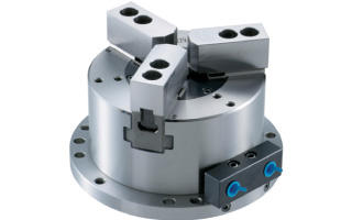
Stationary power chuck with built-in cylinder
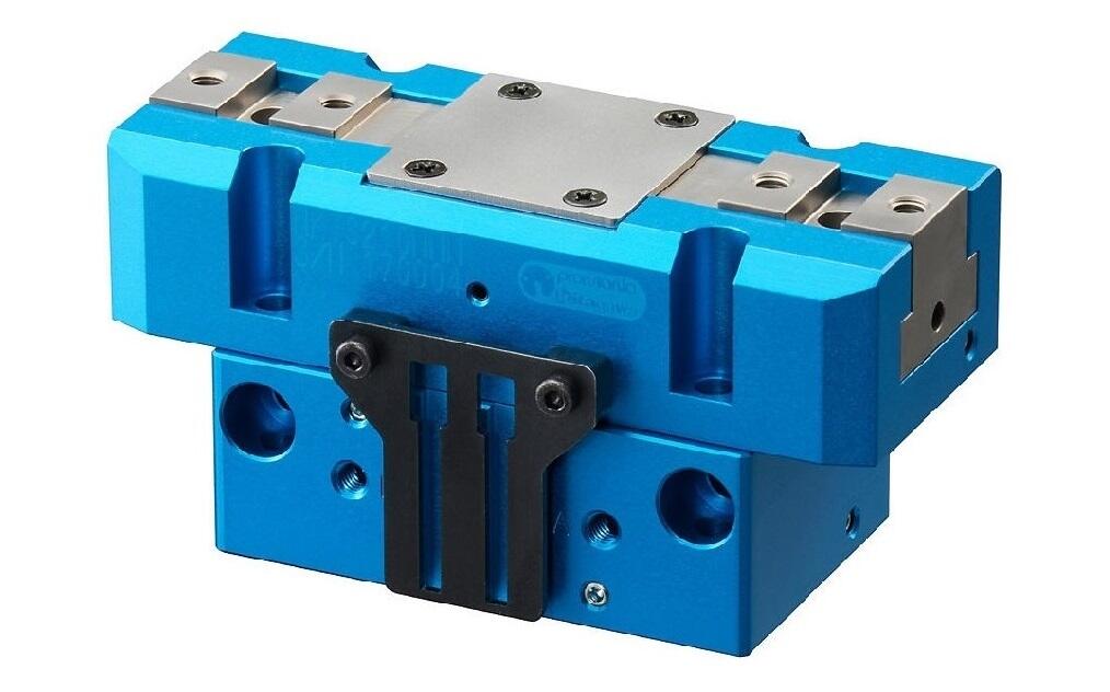
Kitagawa's original grippers with high-quality and high-durability
Strongly support factory automation and unmanned operation

Various catalogues can be downloaded.

Various flyers can be downloaded

Information on discontinued products is posted.